Constructing the Turbidostat
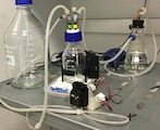
The turbidostat comprises several subsystems that work together to maintain continuous culture. A custom printed circuit board (PCB) carries out turbidity measurements by controlling an LED light source and detecting the faint scattered light signal from the culture. This PCB also controls pumps that add new media to the culture. A 3D-printed housing holds the scattered light detector firmly in place on the side of the growth chamber, an ordinary glass media bottle. Fluidics hardware, consisting of readily available plastic fittings and silicone tubing, delivers media along with sterile air to the growth chamber, and removes waste.
Electronics
The electronics comprise a custom printed circuit board that is assembled, and then connected to a pre-built microcontroller, an Adafruit Feather M0. The PCB can be ordered from a fabrication service, and a collection of electronic components are then soldered onto the PCB. This includes circuits for turbidity measurement by light scattering, along with circuits that allow the microcontroller to drive the pump motors. The scattered light detector itself is mounted on the bottom of the PCB, while the illumination LED is connected through a pair of wires allowing it to be mounted on the side of the growth chamber. A barrel jack connector is used to connect the PCB to a wall adaptor supplying enough current to run the pump motors.
The microcontroller attaches to the circuit board using “headers” – conductive metal pins soldered to the microcontroller board that fit into aligned sockets installed on the custom PCB. The microcontroller has a USB connector that allows it to be programmed using Arduino software on an ordinary computer, and also to report data while it is running.
Housing
The custom PCB and microcontroller are mounted in a custom 3D printed housing, which attaches to a 3D printed band that enricles the growth chamber. The entire housing and band are painted very flat black in order to minimize unwanted, background reflections or stray light. The light detector (photodiode) fits into a narrow hole on the band, while the LED is mounted in another hole situated on the side of the band. A sterilized growth chamber is seated into the band, which holds it in place and provides stable turbidity measurements.
Pump
Peristaltic pumps offers two substantial advantages in the turbidostat. Firstly, the fluid is never exposed to the pump itself, only to the thin silicone tubing that fits into the pump. Thus, the tubing can be sterilized easily and there is no need to sterilize the electrical or mechanical parts of the pump. Secondly, the peristaltic pump delivers a very reproducible amount of liquid each second it is switched on, making it easy to control the rate of media delivery precisely.
The peristaltic pump is mounted in a custom 3D printed stand. We connect the pump motor to the PCB using a cable with a JST connector. This connector is polarized, ensuring that the pump cannot be connected backwards. We use a screw terminal to connect one short end of the JST cable to the PCB, and another screw terminal to connect a longer length of cable to the pump and housing.
Fluidics
The growth chamber and the media reservoir are both built using standard glass media bottles with GL45 caps having threaded ports, often used for HPLC. The growth chamber has rigid plastic tubing extending into the culture for aeration, inoculation / sampling, and waste. On the outside of the cap, we attach short lengths of silicone tubing to the top of the rigid plastic using silicone sealant. Other than this connection, we use barbed Luer-lock connectors for all of the tubing.
The growth chamber receives a steady stream of sterile air that passes first through a 0.2 µm disc filter and then bubbles through sterile water. The air scrubber is constructed from a side-arm flask with rigid tubing extending down through a stopper. The disk filter is attached on the top, and sterile humidified air emerges from the side connector. Silicone tubing connects this side connector to the air inflow port on the growth chamber lid. The air bubbles through the culture and maintains a constant flow and slightly positive pressure. This air flows continuously out of the waste line, which we configure to pass through an S-shaped trap and then hang freely in a waste recepticle. When media addition raises the culture volume to the level of the bottom of the waste tube, excess culture is forced out by the air flow. The combination of continuous airflow and the S-shaped bend protects the culture from contamination.
Another piece of silicone tubing delivers media from the reservoir. This tubing has a section of thin peristaltic pump tubing with thicker tubing on each side. The far end connects to the media reservoir, where a long, semi-rigid tube withdraws media. The reservoir also has a filtered vent for pressure equalization and a third port to add sterilized media.
Design files
The following types of files can be found in the
design
directory:
| Extension | Description |
|---|---|
.brd |
Eagle PCB layout file, accepted directly by many PCB fabricators |
.sch |
Eagle circuit schematic file |
.f3d |
Autodesk Fusion 360 3D design file |
.stl |
General computer-aided design file format, accepted by many 3D printers |
.ino |
Arduino source file, essentially a C++ source |
.h |
Arduino header file, essentially a c++ header |
The key files needed to produce a turbidostat are:
| File | Description |
|---|---|
design/circuit/band-single-feather.brd |
PCB layout file for custom circuit, provided to PCB fabricator |
design/circuit/band-single-feather-bom.csv |
CSV format Bill of Materials listing individual components and part numbers |
design/housing/250-ml-band.stl |
STL file for 3D printing a band for a 250 ml growth chamber |
design/housing/500-ml-band.stl |
STL file for 3D printing a band for a 500 ml growth chamber |
design/housing/feather-nephel-housing.stl |
STL file for 3D printing the PCB housing |
design/housing/motor-mount.stl |
STL file for 3D printing a pump motor mount |
design/firmware |
A collection of .ino and .h Arduino source files to compile the controller software |